VXLAN Data Plane
When you configure the VXLAN protocol, your switch forwards traffic differently depending on the destination MAC address and learned VXLAN topology. If the source and destination MAC addresses are available on the same VLAN and the switch has already learned those MAC addresses, it forwards traffic locally with no VXLAN encapsulation.
If your switch has an entry in the local VXLAN VTEP tunnel table that indicates that the destination MAC address is behind a remote VTEP, it encapsulates the frames in the appropriate VXLAN header and then forwards them to the remote VTEP. The remote VTEP decapsulates the VXLAN packet and forwards the inner frame to the port where the recipient is connected. If the local VTEP does not know the destination MAC address, further steps depend on the control plane implementation.
There are three possible scenarios:
Unicast frames with an unknown destination MAC address are dropped.
Unicast frames with an unknown destination MAC address are forwarded using a predefined multicast group.
Unicast frames with an unknown destination MAC address are replicated to all corresponding VTEPs using multiple unicast packets.
VXLAN Unicast Forwarding Layer 2 Packet Flow
When your VTEPs have collected all the necessary information about end host and virtual machine MAC addresses, you can start traffic forwarding.
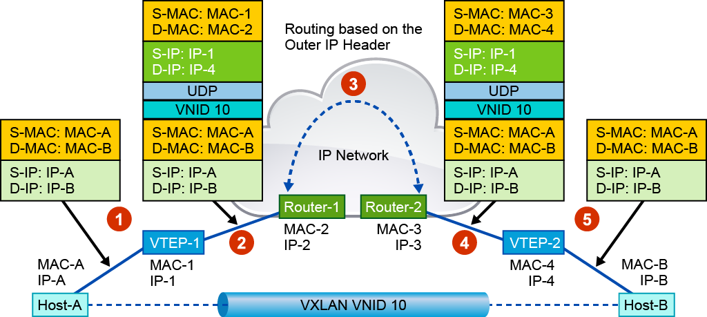
In this scenario, you have two end hosts: Host-A and Host-B reside in the same subnet but are behind different VTEPs. Host-A sends a Layer 2 frame to Host-B.
The traffic forwarding process in this case has the following steps:
Host-A sends a Layer 2 frame with its own source MAC and IP addresses; the destination MAC and IP addresses are the addresses of Host-B. Because both hosts belong to the same subnet, traffic behavior looks like they reside on the same switched physical network. Based on the switching tables of local switches, that original frame will come to the local VTEP-1.
VTEP-1 looks in its local MAC address table and finds that the destination MAC address is located behind remote VTEP-2. VTEP-1 encapsulates the original Layer 2 frame with VXLAN, UDP, IP, and Ethernet headers and sends it through the transport IP network to the remote VTEP-2. Because Host-A belongs to VXLAN 10, the VTEP uses VNID 10 in the VXLAN header. In the outer IP header, VTEP-1 uses its own IP address as the source and uses the IP address of VTEP-2 as the destination. In the outer Ethernet header, VTEP-1 uses its own MAC address as the source and the MAC address of the next-hop router as the destination MAC address.
The VXLAN packet will travel through the transport IP network from VTEP-1 to VTEP-2.
Router-2 has VTEP-2 as the next hop router. Router-2 forwards the encapsulated packet to the VXLAN tunnel destination.
VTEP-2 decapsulates the packet, verifies its local MAC address table, and forwards the original Layer 2 frame to its final destination, which is Host-B.
VXLAN Unicast Forwarding Layer 3 Packet Flow
When your VTEPs have collected all the necessary information about the MAC addresses of the end hosts and virtual machines, you can start traffic forwarding.
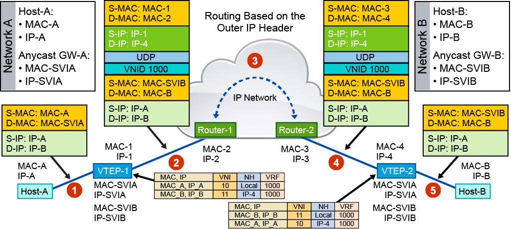
Host-A (attached to VTEP-1) belongs to the Layer 2 virtual network with VNI 10, and Host-B (attached to VTEP-2) belongs to the Layer 2 VNI 11. The subnets for the two networks host different IP address ranges, so the traffic between them is routed.
The reachability information for the two end hosts (for example, the Layer 3 VNI, MAC and IP addresses, and the subnet address of the SVI) has been sent through the MP-BGP EVPN control plane. The ARP and forwarding tables of the source and target switch VTEPs are populated with the end hosts’ reachability information.
The traffic forwarding process in this case has the following steps:
When Host-A sends traffic to VTEP-1, the destination MAC address of the packet is encapsulated with the MAC address of the (distributed IP anycast) gateway.
VTEP-1 does a lookup, notes the VTEP to which Host-B is attached, and checks the VRF (and associated Layer 3 VRF VNI). VTEP-1 VXLAN encapsulates the traffic sent by Host-A and sends it to VTEP-2.
The routed traffic from VTEP-1 to VTEP-2 logically traverses through the Layer 3 VRF VNI 1000. Practically, the traffic traverses through the underlay.
When the packet reaches VTEP-2, VTEP-2 does a control plane lookup, notes that Host-B’s IP address is in VRF 1000, and then does a MAC table lookup for Host-B. After identifying the port to which Host-B is attached, the packet is sent to Host-B.