MP-BGP EVPN Control Plane Overview
MP-BGP EVPN is a standard-based VXLAN control protocol. It introduces control-plane learning for end hosts behind remote VTEPs. It provides control-plane and data-plane separation and a unified control plane for both Layer 2 and Layer 3 forwarding in a VXLAN overlay network.
The MP-BGP EVPN control plane offers eight main benefits:
The MP-BGP EVPN protocol uses industry standards, allowing multivendor interoperability.
It enables control-plane learning of end-host Layer 2 and Layer 3 reachability information, which enables organizations to build more robust and scalable VXLAN overlay networks.
It uses the decade-old MP-BGP VPN technology to support scalable multitenant VXLAN overlay networks.
The EVPN address family carries both Layer 2 and Layer 3 reachability information, thus providing integrated bridging and routing in VXLAN overlay networks.
It minimizes network flooding through protocol-based host MAC and IP route distribution and ARP suppression on the local VTEPs.
It provides optimal forwarding for east-west and north-south traffic and supports workload mobility with the distributed anycast gateway function.
It provides VTEP peer discovery and authentication, mitigating the risk of rogue VTEPs in the VXLAN overlay network.
It provides mechanisms for building active-active multihoming at Layer 2.
With MP-BGP EVPN, VXLAN control plane devices might be MP-IBGP EVPN peers or route reflectors, or MP External BGP (MP-EBGP) EVPN peers. Their operating system software needs to support MP-BGP EVPN so that it can understand the MP-BGP EVPN updates and distribute them to other MP-BGP EVPN peers using the standards-defined constructs. For data forwarding, IP transport devices perform IP routing based only on the outer IP address of a VXLAN encapsulated packet. They do not need to support the VXLAN data encapsulation and decapsulation functions.
Similar to other network routing control protocols, MP-BGP EVPN distributes Network Layer Reachability Information (NLRI) for the network. A unique feature of EVPN NLRI is that it includes both the Layer 2 and Layer 3 reachability information for end hosts that reside in the EVPN VXLAN overlay network. In other words, it advertises both MAC and IP addresses of EVPN VXLAN end hosts. This capability forms the basis for VXLAN-integrated routing and bridging support. VXLAN routing allows you to route traffic between different VXLANs.
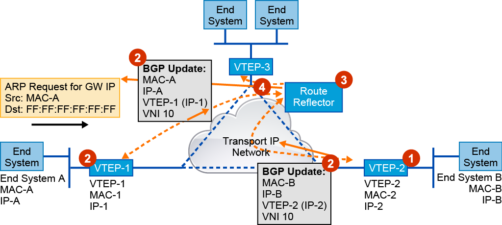
The entire process of MP-BGP EVPN control plane operation includes the following main steps:
A VTEP in the MP-BGP EVPN learns the MAC addresses and IP addresses of locally attached end hosts through local learning. This learning can be based on the local data plane using the standard Ethernet and IP learning procedures: source MAC address learning from the incoming Ethernet frames and IP address learning when the hosts send GARP and Reverse ARP (RARP) packets or ARP requests for the gateway IP address on the VTEP.
After learning the local-host MAC and IP addresses, a VTEP advertises the host information in the MP-BGP EVPN control plane so that this information can be distributed to other VTEPs. This approach enables EVPN VTEPs to learn the remote end hosts in the MP-BGP EVPN control plane. VTEPs advertise EVPN routes through the Layer 2 VPN EVPN address family. The BGP Layer 2 VPN EVPN routes include the following information:
Route distinguisher: This eight-octet number is used to distinguish one set of routes (one VRF instance) from another. It is a unique number that is prepended to each route so that if the same route is used in several different VRF instances, BGP can treat them as distinct routes. The route distinguisher is transmitted along with the route through MP-BGP when EVPN routes are exchanged with MP-BGP peers.
MAC address length: 6 bytes
MAC address: Host MAC address
IP address length: 32 or 128
IP address: Host IP address (IPv4 or IPv6)
Layer 2 VNI: VNI of the bridge domain to which the end host belongs
Layer 3 VNI: VNI that is associated with the tenant VRF routing instance
MP-BGP EVPN uses the BGP extended community attribute to transmit the exported route targets in an EVPN route. When an EVPN VTEP receives an EVPN route, it compares the route-target attributes in the received route to its locally configured route-target import policy to decide whether to import or ignore the route. This approach uses the decades-old MP-BGP VPN technology (RFC 4364) and provides scalable multitenancy, in which a node that does not have a VRF instance locally does not import the corresponding routes.
When a VTEP switch originates MP-BGP EVPN routes for its locally learned end hosts, it uses its own VTEP address as the BGP next hop. This BGP next hop must remain unchanged through the route distribution across the network because the remote VTEP must learn the originating VTEP address as the next hop for VXLAN encapsulation when forwarding packets for the overlay network.
The route reflector works like a neighbor relationship aggregation point and provides BGP update exchange.
As a result of the MP-BGP EVPN control plane operation, every VTEP knows how to reach every end system.
VTEP Peer Discovery and Authentication in MP-BGP EVPN
Before MP-BGP EVPN, VXLAN did not have a control protocol-based VTEP peer-discovery mechanism or a method for authenticating VTEP peers. These limitations present major security risks in real-world VXLAN deployments because they allow easy insertion of a rogue VTEP into a VNI segment to send or receive VXLAN traffic.
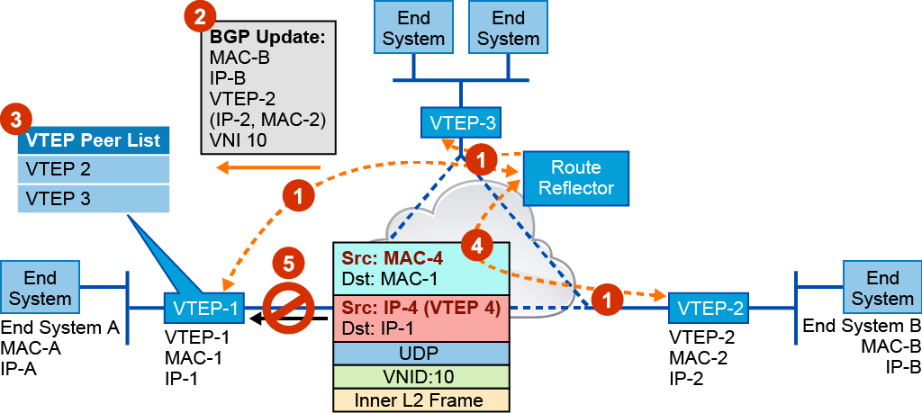
With the MP-BGP EVPN control plane, VTEPs use the following peer discovery and authentication mechanism:
The VTEP device first needs to establish BGP neighbor adjacency with other VTEPs or with Internal Border Gateway Protocol (IBGP) route reflectors. In addition to the BGP updates for end-host NLRI, VTEPs exchange the following information about themselves through BGP:
Layer 3 VNI
VTEP address
Router MAC address
When a VTEP receives BGP EVPN route updates from a remote VTEP BGP neighbor, it adds the VTEP address from that route advertisement to the VTEP peer list.
Local VTEP uses this VTEP peer list as an allow list of valid VTEP peers.
If your local VTEP receives a packet from another VTEP that is not on that allow list, it considers the source of the packet as invalid or unauthorized.
Your local VTEP will discard VXLAN encapsulated traffic from an invalid VTEP.
For additional security, you can apply the existing BGP MD5 authentication to the BGP neighbor sessions so that switches cannot become BGP neighbors to exchange MP-BGP EVPN routes until they successfully authenticate each other.
Distributed Anycast Gateway in MP-BGP EVPN
In MP-BGP EVPN, you can configure any VTEP in a VNI as the distributed anycast gateway for end hosts in its IP subnet. In this case, all VTEPs will have the same virtual gateway IP address and the virtual gateway MAC address.
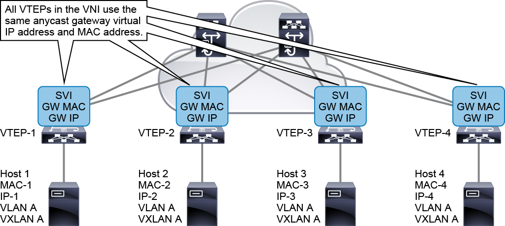
With the EVPN anycast gateway function, end hosts in a VNI can always use their local VTEPs for this VNI as their default gateway to send traffic outside of their IP subnet. This capability enables optimal forwarding for northbound traffic from end hosts in the VXLAN overlay network. A distributed anycast gateway also offers the benefit of seamless host mobility in the VXLAN overlay network. Because the gateway IP and virtual MAC address are the same on all VTEPs within a VNI, when an end host moves from one VTEP to another VTEP, it does not need to send another ARP request to relearn the gateway MAC address.
ARP Suppression in MP-BGP EVPN
To reduce network flooding caused by broadcast traffic from ARP requests, the MP-BGP EVPN control plane provides an ARP suppression feature. When you enable the ARP suppression feature for a VNI, each VTEP maintains an ARP suppression cache table for known IP hosts and their associated MAC addresses in the VNI segment.
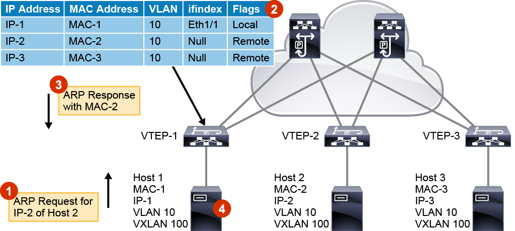
When an end host in the VNI sends an ARP request for another end host IP address, its local VTEP intercepts the ARP request and checks for the IP address from the ARP request in its ARP suppression cache table. If it finds a match, the local VTEP sends an ARP response on behalf of the remote end host. The local host learns the MAC address of the remote host in the ARP response. If the local VTEP does not have information about the IP address from the ARP request in its ARP suppression table, it floods the ARP request to the other VTEPs in the VNI. This ARP flooding can occur for the initial ARP request to a silent host in the network. The VTEPs in the network do not see any traffic from the silent host until another host sends an ARP request for its IP address and it sends an ARP response back. After the local VTEP learns about the MAC and IP address of the silent host, the information is distributed through the MP-BGP EVPN control plane to all other VTEPs. Any subsequent ARP requests do not need to be flooded.
Because most end hosts send Gratuitous ARP (GARP) or RARP requests to announce themselves to the network right after they come online, the local VTEP will immediately have the opportunity to learn their MAC and IP addresses and distribute this information to other VTEPs through the MP-BGP EVPN control plane. Therefore, most active IP hosts in the VXLAN EVPN should be learned by the VTEPs through local learning or control plane-based remote learning. As a result, ARP suppression reduces the network flooding caused by host ARP learning behavior.
The entire process of ARP suppression in MP-BGP EVPN consists of the following steps:
Host 1 in VLAN 10 sends an ARP request for the IP address of Host 2 (IP-2).
VTEP-1 intercepts the ARP request and checks its ARP suppression cache. It finds a match for IP-2 in VLAN 10 in its ARP suppression cache.
VTEP-1 sends an ARP response to Host 1 with MAC-2.
Host 1 learns the IP-2 and MAC-2 mapping.
VXLAN EVPN Multi-Site
VXLAN EVPN Multi-Site architecture is a VXLAN BGP EVPN design that is based on overlay networks. It allows interconnection of multiple distinct VXLAN BGP EVPN fabrics or overlay domains, and new approaches to fabric scaling, compartmentalization, and DCI.
When you build one large data center fabric per location, various operations and failure containment challenges exist. By building smaller compartments of fabrics, you could improve the individual failure and operation domains, but the complexity of interconnecting these compartments makes the pervasive introduction of such concepts impossible, specifically when Layer 2 and Layer 3 extension are required.
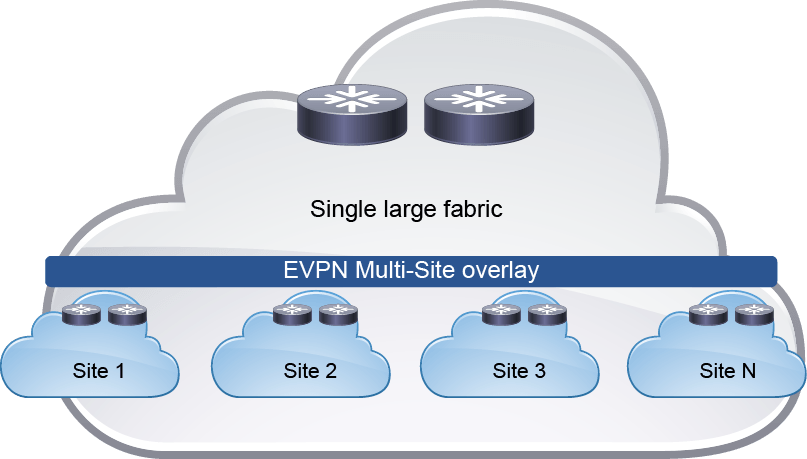
As with the compartmentalization and scale-out within a data center, EVPN Multi-Site architecture was built with DCI in mind. The overall architecture allows single or multiple sites per data center to be positioned and interconnected with single or multiple sites in a remote data center. With seamless and controlled Layer 2 and Layer 3 extension using VXLAN BGP EVPN within and between sites, the capabilities of VXLAN BGP EVPN itself have been increased. The new functions that are related to network control, VTEP masking, and BUM traffic enforcement are only some of the features that help make EVPN Multi-Site architecture the most efficient DCI technology.
The main functional component of the EVPN Multi-Site architecture is the border gateway, or BGW. BGWs separate the fabric-side (site-internal fabric) from the network that interconnects the sites (site-external DCI) and masks the site-internal VTEPs.
Commonly, an EVPN Multi-Site deployment consists of two or more sites that are interconnected through a VXLAN BGP EVPN Layer 2 and Layer 3 overlay. In the scenario in the figure, the BGW is connected to the site-internal VTEPs (usually through spine nodes) and to a site-external transport network that allows traffic to reach the BGWs at other, remote sites. The BGWs at the remote sites have site-internal VTEPs behind them. Only the underlay IP addresses of the BGWs are seen inside the transport network between the BGWs. The site-internal VTEPs are always masked behind the BGWs.
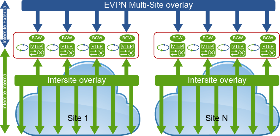
From a BGW perspective, the role of the site-internal VTEPs is to share the common VXLAN and BGP-EVPN functions. To interoperate with a BGW, a site-internal node must support the following functions:
VXLAN with PIM ASM or ingress replication (BGP EVPN Route Type 3) in the underlay
BGP EVPN Route Type 2 and Route Type 5 for the overlay control plane
Route reflector capable of exchanging BGP EVPN Route Type 4
VXLAN Operation, Administration, and Maintenance (OAM)-capable devices for end-to-end OAM support
From the point of view of the site-external network, no specific requirements are demanded apart from IP transport reachability between the BGWs and accommodation of an increased MTU packet size. The BGWs always use ingress replication for Layer 2 BUM traffic between BGWs in different sites, but they can use PIM ASM or ingress replication within a given site. This capability provides flexibility for existing deployments and transport independence for the site-external network.
The BGW performs the internal-to-external site-separation procedure locally. Therefore, the BGW does not require a neighboring device to perform this function. Just as a traditional VTEP can connect from a site-internal network to a BGW, a traditional VTEP can also connect to a BGW from a site-external network. That is, a BGW at the source site does not require a neighboring BGW at the destination site; a traditional VTEP is sufficient. This flexibility is built into the BGW and allows deployments beyond the traditional EVPN Multi-Site pairings.
Note that even though a traditional VTEP would work to connect to a BGW from a site-external network, such externally connected VTEPs would not perform any extended BGW functions such as site-internal VTEP masking.
With EVPN Multi-Site architecture, two placement locations can be considered for the BGW. A dedicated set of BGWs can be placed at the leaf layer, with the BGWs connected to the spine just like any other VTEP in the fabric (site-internal VTEPs). Alternatively, BGWs can be colocated on the spine of the fabric. If the BGW is on the spine, many functions are overloaded together: for instance, the route-reflector,, east-west traffic, and external connectivity functions. In this case, you need to consider additional factors that are related to scale, configuration, and failure scenarios.
The anycast BGW (A-BGW) performs the BGW function. The anycast BGW (A-BGW) allows the BGWs to be scaled horizontally in a scale-out model and without sharing the issues of interdevice dependencies. As of Cisco NX-OS Release 7.0(3)I7(1), the A-BGW is available on the Cisco Nexus 9000 Series cloud-scale platforms (Cisco Nexus 9000 Series EX and FX platforms), with up to four A-BGWs available per site.
The name “A-BGW” refers to the sharing of a common VIP address or anycast IP address between the BGWs in a common site. This document also uses the virtual IP address to refer to the EVPN Multi-Site anycast IP address.
The virtual IP address on the BGW is used for all data-plane communication leaving the site and between sites when the EVPN Multi-Site extension is used to reach a remote site. The single virtual IP address is used both within the site to reach an exit point and between the sites, and the BGWs always use the virtual IP address to communicate with each other. The virtual IP address is represented by a dedicated loopback interface that is associated with the network virtualization edge (NVE) interface (multisite border-gateway interface loopback100).
With this approach, and with the existence of an ECMP network, all BGWs are always equally reachable and active for data-traffic forwarding. The underlay transport network within or between the sites is responsible for hashing the VXLAN traffic among the available equal-cost paths. Considering the entropy of VXLAN, this approach avoids polarization and increases resiliency. If one or more BGWs fail, the remaining BGWs still advertise the virtual IP address and are therefore immediately available to take over all the data traffic. The use of anycast IP addresses or virtual IP addresses provides network-based resiliency, instead of resiliency that relies on device hellos or similar state protocols.
In addition to the virtual IP address or anycast IP address, every BGW has its own individual personality, which the primary VTEP IP (PIP) address (source-interface loopback1) represents. In the BGW, the PIP address is responsible for managing BUM traffic. Every BGW uses its PIP address to perform BUM replication in the multicast underlay or when advertising BGP EVPN Route Type 3 (inclusive multicast) for ingress replication. Therefore, every BGW has an active role in BUM forwarding. Like the virtual IP address, the PIP address is advertised to the site-internal network and to the site-external network. The PIP address is used to manage BUM traffic between BGWs at different sites, because EVPN Multi-Site architecture always uses ingress replication for this process.
The PIP address is also used in two additional scenarios that are closely related.
If the BGW provides external connectivity with VRF-Lite next to the EVPN Multi-Site deployment, routing prefixes that are learned from the external Layer 3 devices are advertised inside the VXLAN fabric with the PIP address as the next-hop address. From the BGW’s point of view, these externally learned IP prefixes are considered to originate locally from a BGW and use the BGP EVPN address family. This process creates an individual BGP EVPN Route Type 5 (IP prefix route) from every BGW that learned a relevant IP prefix externally. In the best case, your site-internal network has an ECMP route to reach non-EVPN Multi-Site networks.
A closely related scenario is the case in which the BGW advertises an IP prefix with its own PIP address through local connectivity. An endpoint can be directly connected to a BGW, but its IP address can be learned only through routing on a physical interface or subinterface. The all-active connection of Layer 4 through Layer 7 network services (for example, firewalls and load balancers) can be achieved through ECMP routing with a static or dynamic routing protocol.
Every A-BGW actively participates in the forwarding of BUM traffic. Specifically, the designated-forwarder function for BUM traffic is distributed on a per-Layer 2 VNI basis. To synchronize the designated forwarders, BGP EVPN Route Type 4 (Ethernet segment route) updates are exchanged between the BGWs within the same site.
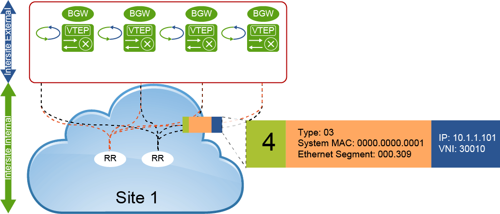
To participate in the designated-forwarder election, the configuration of the same site ID is required. This ID is defined as part of the BGW configuration (evpn multisite border-gateway site-id). In addition to the site ID, the same Layer 2 VNI must be used to elect the designated forwarder from among the eligible BGWs.
The designated-forwarder assignment is performed on a per-Layer 2 VNI basis, using a round-robin process to distribute assignments equally. An ordinal list of PIP addresses is used, and based on the entire Layer 2 VNI order of configuration or ordinal list, the designated-forwarder role is distributed in a round-robin fashion.
To exchange the designated-forwarder election messages between the BGWs, BGP EVPN peering is required because the election messages consist of BGP EVPN Route Type 4 advertisements. The BGW would usually peer with a site-internal (fabric) route reflector, which also has all the endpoint information from within the site-internal VTEPs. With the route reflector already present in the fabric, and with all VTEPs, including the BGW, peering with it, the exchange of designated-forwarder election messages is achieved.
In cases in which no route reflector exists, or in which the route reflector is not capable of relaying BGP EVPN Route Type 4, an IBGP session can be considered as an alternative. The IBGP peering must be EVPN address family-enabled and there must be a full mesh established between the loopback interfaces of the BGWs.
Multicast Control Plane (Flood and Learn)
The second type of VXLAN control plane operation is flood-and-learn mode, which uses a multicast-enabled transport IP network. In this mode, the process of traffic forwarding triggers end-host information learning and VTEP discovery. There is no control protocol to distribute end-host reachability information among VTEPs.
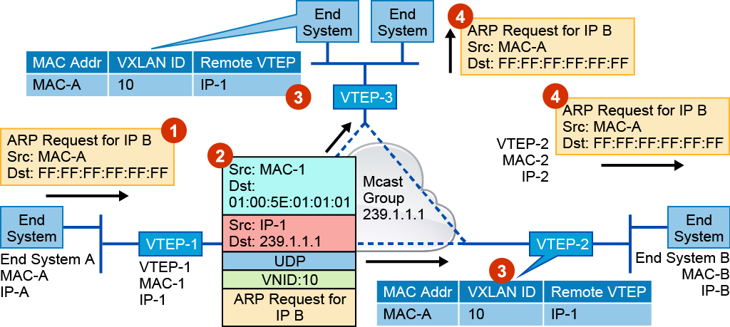
For the flood-and-learn control plane, the transport IP infrastructure must support ASM. Every VTEP that you configure for a specific VXLAN with a certain VNI will join the same multicast group. Initially, each VTEP will only learn MAC addresses of its local end hosts and virtual machines. To learn remote MAC addresses, your VTEP will use the conversational MAC address learning technique.
The following describes how this mechanism works. For example, End System A needs to send some data to End System B.
End System A generates an ARP request to discover the MAC address of End System B. The ARP request is sent with the source MAC address MAC-A and the destination MAC address is broadcast (FF:FF:FF:FF:FF:FF). When the VTEP receives the Layer 2 frame, it will look in its local table for the proper destination for this frame, which can be a local interface or remote VTEP IP address.
In BUM traffic, the VTEP will encapsulate the original Layer 2 frame and send it over the multicast group that you configured for the specific VNI. The VTEP adds VXLAN, outer UDP, IP, and Ethernet headers to your original ARP request. In the outer IP header, you can see the multicast address (239.1.1.1) as the packet destination IP address that allows you to deliver that packet to all VTEPs that work with the same VNI. For the outer destination MAC address, your VTEP also uses the multicast MAC address (01:00:5E:01:01:01). The VTEP obtained this value from a known IP multicast address. Then the VTEP forwards the encapsulated Layer 2 frame to the multicast rendezvous point, which forwards a copy of the packet to every VTEP that has joined the multicast group.
Each VTEP will receive and decapsulate the VXLAN packet and learn MAC address of End System A (MAC-A) pointing to the remote VTEP address (IP-1).
Each VTEP forwards the ARP request to its local network. At this moment, End System B receives the ARP request from End System A. The next step is to send an ARP response back to End System A.
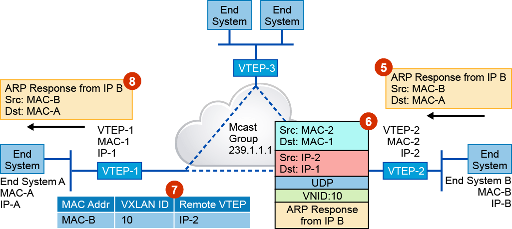
End System B generates a unicast ARP response with the source MAC address, MAC-B, and the destination MAC address, MAC-A.
When VTEP-2 receives the ARP response, it will look in its local table and will find a corresponding entry. Now VTEP-2 knows that traffic going to End System A must be sent to the VTEP-1 address. VTEP-2 encapsulates the ARP response with a VXLAN header and sends the unicast packet to VTEP-1.
VTEP-1 receives and decapsulates the original ARP response. At this moment, VTEP-1 learns the source MAC address of End System B and creates an entry in its local table with the information about how to reach End System B.
Then VTEP-1 sends an original ARP response frame to End System A.