Layer 2 and Layer 3 VXLAN Overlay
Businesses face the challenge of providing very high availability for applications while keeping operating expenses low. Applications must be available anytime and anywhere with optimal response times. Virtualization, multitenancy, and other growth have placed increasing demands on the network. However, in cases where server clustering and workload mobility are crucial, the network must extend Layer 2 connectivity across routing domains. This connectivity must be provided without making changes to end systems or by compromising the stability of the overall network.
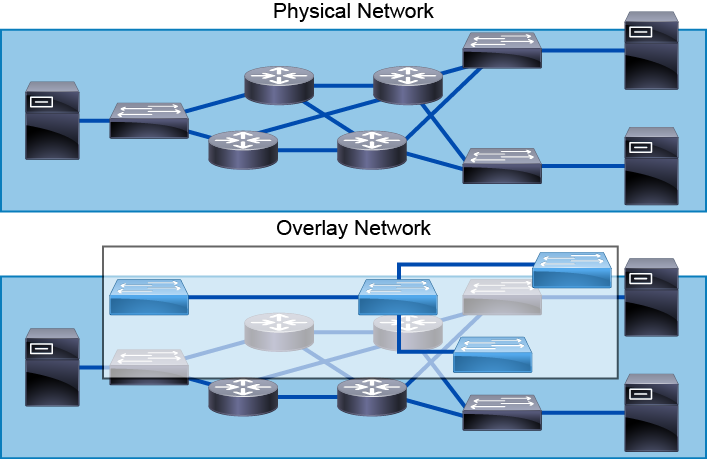
Overlays are independent of the underlying infrastructure technologies and services. They typically do not impose any restrictions on the underlying infrastructure, as long as it is capable of transporting IP packets. Overlays can take advantage of all the capabilities of the underlying transport network, such as fast convergence, load balancing, and multicast replication.
You can deploy overlay networks in private, public, and hybrid cloud environments in the data center to support these use cases:
Simplified management: Use a single point of management to provide network resources for multitenant clouds without the need to change the physical network.
Multitenancy at scale: Provide scalable Layer 2 networks for a multitenant cloud that extends beyond 4000 VLANs. This capability is very important for private and public cloud-hosted environments.
Workload-anywhere capability (mobility and reachability): Optimally use server resources by placing the workload anywhere and moving the workload anywhere in the server farm as needed.
Forwarding-topology flexibility: Add arbitrary forwarding topologies on top of a fixed routed underlay topology.
Types of Overlays
There are two types of network overlays: Layer 2 overlays and Layer 3 overlays. You can choose the appropriate option based on your goals and specific use case. The figure shows an example of a Layer 2 overlay on the left and a Layer 3 overlay on the right.
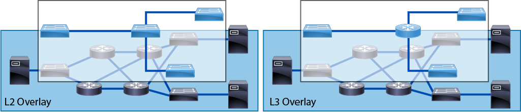
Layer 2 overlays emulate a Layer 2 LAN segment. The forwarding process uses Ethernet frame headers and can therefore transport both IP and non-IP packets. The overlay creates a single subnet (single Layer 2 domain). Layer 2 overlays are useful in an environment where workload mobility is necessary. The overlay can emulate a particular physical topology. The disadvantage of Layer 2 overlays is that the Layer 2 domain becomes wider, and therefore the flooding domain becomes bigger as well.
Layer 3 overlays are useful when you want to transport IP packets but you also want to abstract the underlying IP infrastructure. Layer 3 overlays are handy when you need IP mobility. You can also use them to carry IPv4 traffic over an IPv6 infrastructure or IPv6 over an IPv4 infrastructure.
VXLAN Overlay
A key benefit of virtualization is the ability to move VMs among data center servers while the VM is in service. To support mobility, VMs must remain in their native IP subnet, which ensures continuous network connectivity from the VM to users. The three drivers for VXLAN in traditional networks are great scalability, isolation for multitenancy, and any-to-any Layer 2 communications.
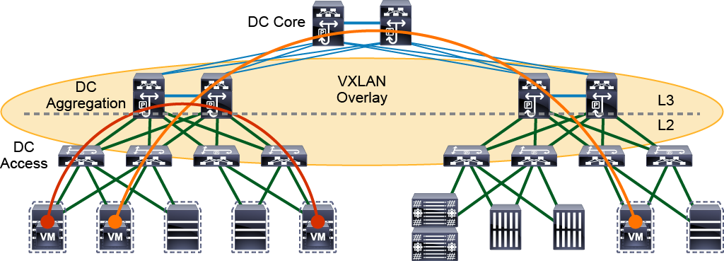
VXLAN provides a unique network ID called a VXLAN Network Identifier (VNI), or virtual network identifier, which provides a tunnel for transporting the original payload. The VXLAN VNI tunnel (or overlay) keeps the traffic within it separate from other traffic in other VXLANs, similar to a VRF or VPN isolation. This approach provides multitenancy in terms of security and scale.
The VXLAN creates LAN segments by using an overlay approach with MAC-in-UDP encapsulation and a 24-bit segment identifier in the form of a VXLAN ID.
VXLAN technology has the following characteristics:
Uses MAC-in-UDP/IP encapsulation.
Can work on hypervisor-based virtual switches and on physical switches.
Uses ECMP to achieve optimal path usage over the transport network.
VXLAN Tunnel End Point
VXLAN encapsulation carries the original Layer 2 frame from the VM or physical host. The VTEP is an entity that originates or terminates a VXLAN tunnel.
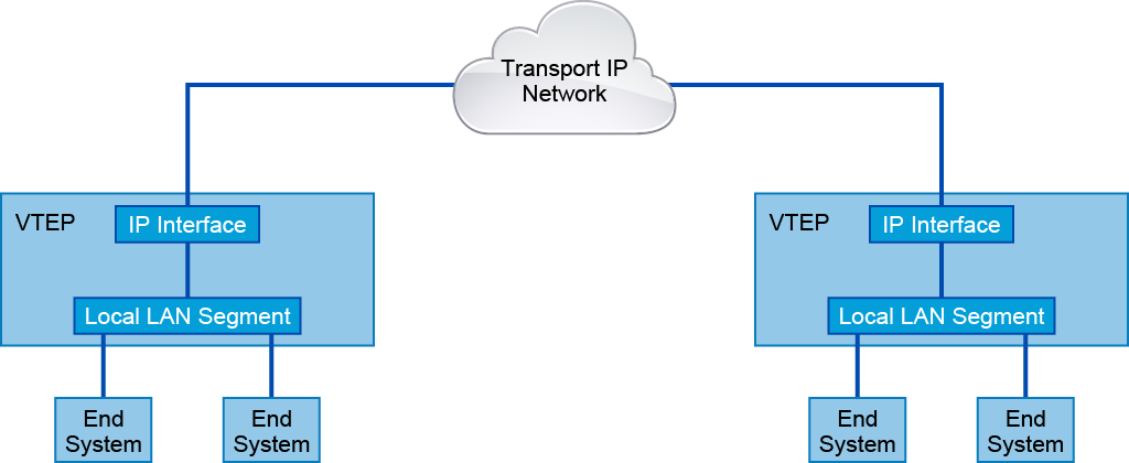
The VTEP encapsulates the frame and sends it through the transport network to the destination VTEP. That VTEP decapsulates the frame and sends it to the final destination. From the transport network perspective, you can use any IP-capable device to send a VXLAN-encapsulated Layer 2 frame.
Each VTEP has two interfaces: one interface provides a bridging function for local hosts (can be a trunk port to the access switch); the other has an IP identification in the core network for VXLAN encapsulation and decapsulation. A VTEP is commonly implemented in a hypervisor, but can exist on a physical switch or physical server and can be implemented in software or hardware. Each VTEP has one or more IP addresses. These addresses work as the source IP address in the packet that contains the original Layer 2 frame and goes through the transport network. The encapsulation carries the VXLAN identifier to isolate each Layer 2 network from another Layer 2 network.
You can implement VXLAN technology on both hypervisor-based virtual switches and on physical switches. On a hypervisor, it provides scalable VM deployments. On physical switches, it allows you to bridge VXLAN segments back into VLAN segments. In these cases, the physical switch instantiates a VTEP and functions as a VXLAN gateway. A physical switch that acts as a VXLAN gateway allows overlays to be extended between virtual machines and bare metal servers.
Because VXLAN uses UDP or IP encapsulation, you can apply ECMP and load-balance network workload using all available paths with the same route metric.
VXLAN MP-BGP EVPN Control Plane
The scalability of the overlay network depends on its ability to handle BUM data. The control plane of overlay network technology defines how to handle BUM traffic. In VXLAN, the standard does not describe the control plane signaling protocol for determining the location of end points. Therefore, you can choose the control plane implementation that fits your specific network environment.
The two most widely used control planes for VXLAN technology with Cisco equipment are as follows:
MP-BGP EVPN control plane
Multicast control plane (flood and learn)